3D Laser Scanning to AutoCAD Conversion: Key Metrics for Success

3D Laser Scanning to AutoCAD Conversion: Key Metrics for Success

Introduction to 3D Laser Scanning and AutoCAD Conversion

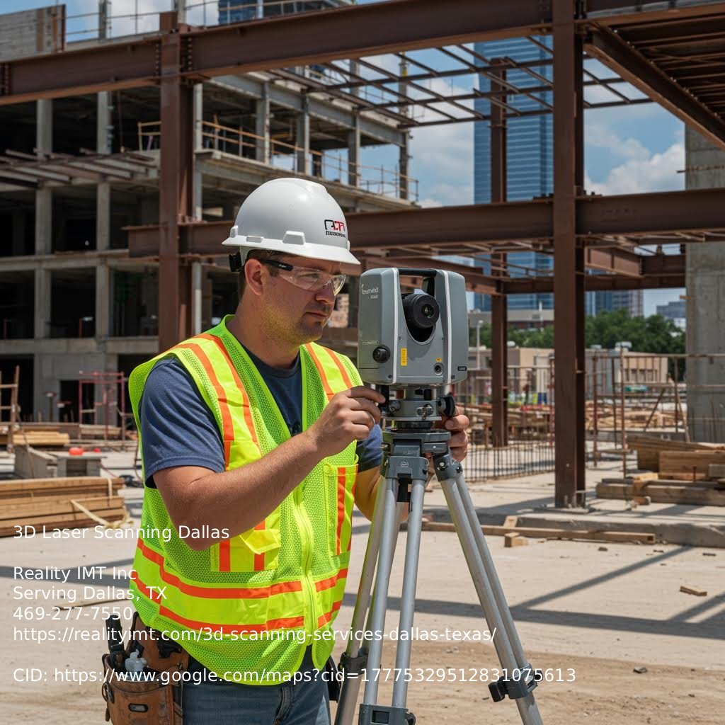
3D laser scanning captures physical spaces by collecting millions of precise measurements using LiDAR. The scanner creates a dense point cloud—a digital copy of the environment. Technicians then turn this raw data into AutoCAD files. When precision matters most in your construction plans 3D laser scanning services Dallas provides fast and detailed digital capture to support design, renovation, and construction decisions.. In Dallas, where building renovations and upgrades happen often, this process supports many architecture, engineering, and construction projects.

AutoCAD files from 3D scans are accurate to fractions of an inch. That matters when working with older buildings that lack reliable plans. The output can include 2D floor plans, elevations, sections, or full 3D models. These files guide design, permitting, clash checks, and construction planning.

Teams can’t easily use raw point clouds in their workflows. The files are too large and complex. AutoCAD drawings are smaller, easier to use, and work well with most design and BIM tools. So, converting scan data into CAD is a must.

Problems can happen if the scan resolution is too low or if the person doing the conversion doesn’t understand the project. Scanning a mechanical room for MEP work is not the same as documenting a historic façade. If the AutoCAD file misses key details, delays or rework can follow. Here is why it helps to work with teams who know how to scan and model for Dallas-specific projects.

Who Uses 3D Laser Scanning in Dallas?

In Dallas, many professionals need accurate AutoCAD files from 3D laser scans. Architects use them to plan renovations or additions without guessing what’s behind walls or above ceilings. General contractors need them to confirm site conditions before bidding or starting work. Structural and MEP engineers depend on them to plan load paths, ductwork, and pipe routing in tight spaces. Property owners want to know exactly what they have before investing in a major retrofit. Here is why timing and accuracy matter. The scan-to-CAD process creates 2D floor plans, elevations, and sometimes full 3D models that match real-world dimensions down to fractions of an inch. That level of detail helps avoid costly mistakes. If a beam is off by two inches in your drawing and you build around it, you’ll face problems during construction. Many older buildings in Dallas have undocumented changes—past renovations, shifted walls, or dropped ceilings. Scanning captures current conditions. Without it, teams rely on outdated drawings or tape-measured notes, which are often wrong. Let’s break it down. The process starts with a crew scanning the building and collecting millions of data points. That point cloud becomes usable AutoCAD files. It takes time, and results vary. If the scan misses a room or has poor lighting or obstructions, the final drawings will show those gaps. So, the quality of the AutoCAD file depends on how well the scan was done.

The Workflow: From 3D Scans to AutoCAD Drawings

Point Cloud

The process starts by capturing a point cloud with 3D laser scanners. These scanners collect millions of data points that show the exact shape of a structure or site. The raw point cloud usually comes in formats like .e57, .las, or .rcs, depending on the scanner. Before bringing anything into AutoCAD, clean up the point cloud. That means removing noise, aligning scans, and trimming extra data. This step matters because mistakes here carry into the CAD file. Get it right now to avoid problems later.

Software Selection

Picking the right software for scan data matters. Tools like Autodesk ReCap, Leica Cyclone, or FARO Scene help prep and register point clouds before exporting to AutoCAD. Each one works better depending on project size, file type, and output needs. Some connect more easily with CAD platforms. Others focus more on editing or display. The wrong tool can slow things down or cause file issues later. Choose based on how the team works, not just features.

Data Registration

Next, register data from multiple scan points into one coordinate system. This means aligning scans so they form a single, accurate model. Most software offers automatic registration, but manual fixes are often needed to correct drift or misalignment. If this step goes wrong, the AutoCAD file may have gaps or errors. Let’s break it down: even a few inches off in a large Dallas building can mess up floor plans or clash checks. Get it right now to avoid rework later.

Model Extraction

Once the point cloud is clean and aligned, start pulling geometry into AutoCAD. This might mean tracing over the cloud to create 2D plans, elevations, or full 3D models. Depending on the project, teams may use AutoCAD, Revit, or Civil 3D. Decide early how much detail is needed—just walls and windows, or full MEP systems. Too much detail wastes time. Too little leaves out key info. Match the model to the project goals.

File Output

After modeling, export the final files as DWG or DXF. These should be organized with clear layers, labels, and names. When teams like architects and MEP engineers work together, standard formats help avoid mix-ups. Add metadata or reference images if needed. A clean AutoCAD file speeds up later work. A messy one causes delays. Next steps: double-check file structure before sending it out.

Key Success Metrics for 3D Scan to CAD Conversion

When turning 3D laser scans into AutoCAD files, the goal isn’t just a finished drawing—it’s about whether that drawing actually helps. A few things decide if the file is useful or just adds extra work.

Dimensional accuracy comes first. If the CAD file doesn’t match real-world measurements, anything built from it will be wrong. In Dallas, older buildings often don’t match their original plans, so accuracy matters. The scanning team must control surface reflectivity, line-of-sight problems, and registration errors. During modeling, check every deviation against the point cloud, especially in structural and MEP areas.

File compatibility often gets overlooked. If an AutoCAD file won’t open cleanly in Revit or Navisworks, it slows everything down. Layer names, object snapping, and file size all affect how easy it is to use. Drawing clarity matters too. Line weights, labels, and layout help people read the file fast on-site. Messy drawings cause delays.

Turnaround time also counts. Architects and contractors can’t always wait weeks. The process should move quickly but stay careful. Relying too much on automation can lead to missing or oversimplified geometry. Use automation for basic shapes and manual work for complex or important parts.

3D Laser Scanning to AutoCAD Conversion: Key Metrics for Success

Use Case Scenarios by Industry Segment

Creating AutoCAD files from 3D laser scans is a key step when working with existing buildings in Dallas. Whether it’s a commercial renovation, MEP retrofit, or full architectural redesign, the process turns raw scan data into usable 2D floor plans, elevations, site layouts, or 3D models. These files aren’t just drawings. When done right, they’re accurate within millimeters. That matters when planning ductwork through tight ceiling spaces or checking load-bearing walls for changes.

Different teams need different outputs. Structural engineers may want a clean 2D section showing all steel columns and beams. MEP teams often ask for RCPs with lighting fixtures, sprinkler heads, and duct paths. Architects might need full 3D models for space planning or documentation. One scan can support all of these. The difference lies in how the AutoCAD files are built. Layering, naming, and clarity affect how useful the files are later.

Rushing the conversion is a common mistake. Using generic layers, skipping field checks, or relying too much on automated tools leads to rework. Sometimes teams have to redo entire files because the geometry doesn’t match the site. Another issue is poor coordination. If the MEP team needs pipe centerlines but gets outer diameters, they can’t use the drawings.

For teams in Dallas handling renovations, tenant improvements, or reuse projects, accurate AutoCAD files early on save time later. It’s not just about having drawings. It’s about having the right ones, with the right detail, for the right team.

Avoiding Common Pitfalls in CAD Conversion Projects

Converting 3D laser scans into AutoCAD files can go wrong fast. Start with scan quality. If the point cloud is blurry, noisy, or missing surfaces, the CAD drawing won’t be right. Walls may not line up, angles might be off, or key elements could be missing. Check lighting, surface reflectivity, and access before scanning. Bad input means bad output.

Misaligned coordinate systems are another issue. If the scan doesn’t match a known system—like a site survey or building grid—the drawing won’t match the real world. This causes problems on large projects or phased renovations where teams need a shared reference. Always check registration before exporting to CAD.

Modeling can also go off track. Some teams skip details like ductwork or sloped surfaces. Others add too much. Model only what’s needed for the task—whether it’s design, construction, or facility use. Set the level of detail early and follow it.

In Dallas, many buildings have complex retrofits or undocumented changes. Inaccurate CAD files can delay permits and lead to rework. Get the scan right, align it well, and model what matters.

Best Practices for Optimized AutoCAD Output

When you convert 3D laser scan data into AutoCAD files, you're doing more than tracing lines. You're creating a reference model that others rely on—architects, engineers, contractors, and even city offices. So accuracy and clarity matter. First, set up your layering system. This keeps the file usable for others. Assign separate layers for walls, windows, structural elements, and MEP systems. Use clear, consistent names. Skip labels like “Layer1” or “Stuff.” Match names to the project and trade. Now, annotations. These often get rushed, but they matter. If you're delivering 2D plans, make sure dimensions, notes, and callouts are easy to read and placed logically. Keep text styles uniform. Use leaders where needed. Scanned a building in Dallas with ceiling heights that vary by three inches? Call it out. That small detail affects HVAC and lighting later. Let’s talk model organization. Group elements in a way that makes sense. Use blocks for repeated items. Don’t redraw the same column over and over. Avoid exploding geometry—it makes edits harder and files heavier. Last step: check the output against the original point cloud. Misalignments happen. One off-angle wall in CAD can mean a prefab panel won’t fit. That costs money. A clean, organized AutoCAD file sets the stage for everything that comes next. Get it right from the start.

Accuracy Standards and QA Processes

When turning 3D laser scan data into AutoCAD files, accuracy matters. In Dallas, this tech supports commercial renovations, facility upgrades, and historical building records. Clients expect CAD files to match real-world conditions within tight tolerances—usually 1/8" or better. Some projects, like MEP coordination or prefabrication, need even tighter accuracy.

After collecting scan data, teams register and align the point cloud. Small errors can sneak in here. Misaligned scans or noisy data can throw off measurements. Here is why QA checks happen early. Overlays, cross-sections, and spot checks catch problems before modeling starts.

During CAD drafting—whether for 2D floor plans, elevations, or 3D models—teams trace lines and surfaces using the point cloud. Still, mistakes can happen. Someone might snap to the wrong point or assume symmetry that doesn’t exist. That’s where review steps come in. A second or third reviewer checks key dimensions and compares the CAD file to the scan data.

Skipping these checks can cause expensive delays. Misplaced walls, wrong pipe runs, or missing structural parts can lead to rework. So whether you're planning upgrades or modeling a historic façade, treat the conversion as a precision task.

Integrating 3D Scans into BIM and Facility Management

When 3D laser scans become AutoCAD files, you get floor plans, elevations, sections, and 3D models that match real conditions. These files support BIM coordination and long-term building upkeep. In Dallas, this matters most in commercial renovations and reuse projects, where old plans are often missing or wrong. Here is how it works. It starts with a high-resolution site scan. That scan turns into a point cloud. Then, CAD technicians pull out geometry—walls, windows, MEP systems, and structure—into clean AutoCAD files. The result can be 2D DWGs, 3D solids, or both, depending on the project. These files often become the base for Revit models or other BIM tools. Let’s break it down. Skipping QA is a common mistake. If the point cloud doesn’t line up or the CAD file misses real details, you get design clashes, bad fabrication, or permit delays. Another issue is over-modeling. Only include bolts or pipes if they matter to the job. Next steps. Facility managers get quick access to accurate as-builts for repairs or space changes. Architects and engineers guess less during design. Owners face fewer surprises during construction. The goal? Make sure CAD files match the scan data.

Choosing a 3D Laser Scanning Partner in Dallas

Not every 3D scanning provider can deliver usable AutoCAD files. If you're in Dallas and need accurate 2D or 3D CAD drawings from laser scan data, focus on more than just the scanning tools. What matters is how well the point cloud becomes clean, editable AutoCAD files. Here is why experience counts.

Start by asking if the provider has in-house CAD technicians who know architectural and engineering standards. Turning raw scan data into floor plans, elevations, or MEP layouts takes more than exporting. It requires knowledge of tolerances, layering, and how different trades will use the files. If the plans look clean but don’t match real-world needs, you’ll waste time fixing them.

Turnaround time matters too. Some firms promise speed but use offshore drafting teams unfamiliar with North American building systems. That leads to errors. Look for local teams who understand Dallas buildings and how to model them well.

Also, check what formats they deliver. DWG is common, but the files should be organized—clean layers, correct scale, and no extra geometry. If you plan to use Revit later, ask if they can prepare the CAD files to support that.

Next steps: don’t choose based on scan resolution or flashy gear. Ask how they handle the CAD work. That’s what makes the scans useful instead of just expensive images.

Conversion Turnaround Time and Project Scheduling

AutoCAD file creation from 3D laser scans depends on several factors: scan area size, required detail, structure complexity, and file type. A basic floor plan of a 5,000-square-foot open warehouse might take a few days. A multi-level historic building with irregular geometry and requests for 2D elevations, ceiling plans, and a 3D model could take weeks. In Dallas, many projects involve commercial retrofits or older buildings with undocumented changes. That means dense, messy scan data. Sorting it into clean AutoCAD files takes time. Higher detail means more modeling hours. Need both 2D and 3D files? That’s double the work. Many teams underestimate how long post-processing takes. Let’s break it down. You can’t scan on Monday and expect a full CAD set by Friday unless the scope is small. Build in buffer time. Talk with your CAD team before scanning. They’ll want to know which features matter—walls, MEP, floor flatness, ceiling heights, façade details—so they can focus during modeling. Next steps: plan for file review. Even solid CAD files need checking. If your architect or engineer requests changes, that adds days. It’s better to expect that than scramble at the last minute. Smart scheduling keeps the project moving and avoids rushed work that leads to mistakes.

Deliverable Formats and CAD File Customization

When converting 3D laser scans into AutoCAD files, start by choosing the output format. DWG and DXF are the main options. DWG is native to AutoCAD and works best for ongoing design, especially when teams work together. DXF is more open and works well when the recipient doesn’t use AutoCAD. Both support 2D and 3D geometry, but DWG handles more object types and metadata. Level of Detail (LOD) is another key choice. You don’t always need a full 3D model. Early design or feasibility work might only need a floor plan with wall lines and major structures. For construction or MEP coordination, you’ll need more detail—like wall thicknesses, pipe runs, conduit, equipment outlines, and ceiling grids. Scanning teams need clear direction. Without it, you might overpay for extra detail or miss what you need and redo work. Match the output to the project phase. A renovation might need 2D DWG floor plans to fit into current files. A facility manager might want simple 3D DXF files for quick checks. Historic preservation teams often ask for detailed 3D models with annotation layers to show surface conditions. Don’t assume scan-to-CAD is automatic. It’s not. Manual drafting from point clouds still matters, especially when accuracy counts. Misaligned scans or low-quality point clouds can throw off dimensions. So check the source data before drafting begins.

Compliance with Regulations and Standards

When turning 3D laser scans into AutoCAD files, the drawings must meet construction and building codes. These can be local, state, or federal, depending on the structure and location. In Dallas, that might include the International Building Code, ADA rules, or fire safety codes. If the CAD files miss these from the start, you’ll end up fixing them later—on a tight schedule and budget.

The CAD file also needs a clear structure. Layers, naming, and geometry should follow standards like the National CAD Standard (NCS) or project-specific rules. If engineers or architects can’t read or trust the file, the scan loses its value. A messy file means wasted time fixing avoidable errors.

File audit trails matter too. Every step—from scan to CAD—needs a record: what was captured, when, by whom, and what changed. This matters most on large commercial or government jobs. If something goes wrong, you need proof of how the data was handled. Without that, responsibility gets unclear fast.

Here is why this matters: converting 3D scans to AutoCAD isn’t just about drawings. It’s about accurate, code-ready files that hold up under review.

Cost Factors and Return on Investment

AutoCAD file generation from 3D laser scanning involves more than turning a point cloud into a drawing. It includes real costs that affect your budget and schedule. Pricing depends on site complexity, the detail level in the CAD files, and how fast you need them. A simple warehouse is one thing. A mechanical room with dense piping or a historic building with odd geometry takes longer to model. Accuracy matters. Cutting corners on scanning or modeling can lead to files that don’t match real conditions. That means rework, missed dimensions, and construction delays. Those issues often cost more than what you saved. On the other hand, accurate scanning and careful CAD work reduce site revisits and guesswork. That gives architects and engineers a solid base. Turnaround time also affects your return. Some Dallas providers deliver basic 2D floor plans in 48–72 hours. Full 3D models may take a week or more, depending on the scope. Faster service usually costs more, but it can be worth it if your project is waiting on drawings. Here is why it matters: Accurate files save time, prevent mistakes, and help you move ahead with confidence.

Client Success Stories and Case Studies

In Dallas, 3D laser scanning is gaining traction for creating accurate AutoCAD files of existing buildings. It’s not just for architects. Structural engineers, MEP consultants, and property owners use these scans for reliable documentation they can build from. One local firm working on a 1950s warehouse needed as-built drawings before gutting the interior for a mixed-use project. They used 3D scanning to capture every column, beam, and slab edge. That data became layered AutoCAD floorplans and reflected ceiling plans. It saved weeks of manual measuring and helped avoid surprises during demo. Another case involved a hospital in downtown Dallas. Facility managers needed to update mechanical systems, but the original blueprints were outdated and incomplete. Scanning the utility corridors and mechanical rooms gave them current 3D models and 2D MEP drawings in AutoCAD. That helped the design team plan duct reroutes and electrical upgrades without guessing clearances or pipe sizes. These conversions don’t happen automatically. Technicians need to know both the scanning tools and CAD standards. Common problems include ignoring scan resolution or misaligning point cloud data. That leads to inaccurate AutoCAD files, which can throw off measurements by inches and cause real issues during construction. For Dallas-area projects, especially renovations or reuse, accurate AutoCAD drawings from 3D scans are now a must. They help design and construction teams avoid delays, change orders, and rework. Here is why: the scan data needs to be processed by people who understand what the end user actually needs. Otherwise, you end up with files no one can trust.

Call to Action: Start Your 3D Scan to CAD Project

If you're working on a building renovation, tenant improvement, or asset documentation project in Dallas, you need accurate as-built data. 3D laser scanning captures the current site—walls, ceilings, piping, structural elements—and creates point cloud data. But scanning is only the beginning. What you do with the data matters more. AutoCAD file generation turns that point cloud into usable 2D drawings and 3D models. Floor plans, elevations, sections, MEP backgrounds—whatever your team needs to move ahead. Accuracy depends on the quality of the scan and how well the data is converted into CAD. Here is why it matters. If you're in Dallas and need AutoCAD files from 3D scans, work with someone who does this often. An experienced team can manage site access, scan settings, file formats, and CAD layering. They’ll ask the right questions—what to model, how much detail, which formats, and how fast you need it. Watch out for common mistakes. Using old drawings. Scanning too little. Getting CAD files that are accurate but hard to use due to bad layer setup or missing references. Not sure where to begin? Request a quote or set up a site walk. A short call can clear up scope, cost, and timing. It also helps you avoid rework. Whether you're an architect on a deadline or a facility manager documenting a large warehouse, getting the CAD files right the first time saves time and money.